LoRaWAN is Long Range Wide Area Network for wireless communication between devices like Sensor Nodes. Distance between Transimter and Reciver can be about 15 km. This protocol is not super fast data rate. Furthermore the data transmission speed is approx 35 kb/s. What’s more LoRa is not appropriate for services where Real Time processing is priority. So this is perfect solution for IoT, especially Wireless Sensor Nodes.
This article descibe how to sucessfull launch LoRa Module Ebyte E32-433T20DC based on chip Semtech SX1278. This module works in the frequency range 410 – 441MHz. Further the transmitting power of the signal is 20 dBm. Moreover this module have on board high precision crystal oscilator with instudtrial grade. Doubtedly this ensures a low level of deviation. Obviously for communication between Computer and module used UART interface.
COMPONENTS
For this project we need board for prototyping of electronics called breadboard. This thing have fast plug-in plug-out wire connection system. This is very useful but not high precision. Sometime something not working because wire connector poor contact with socket on breadboard.
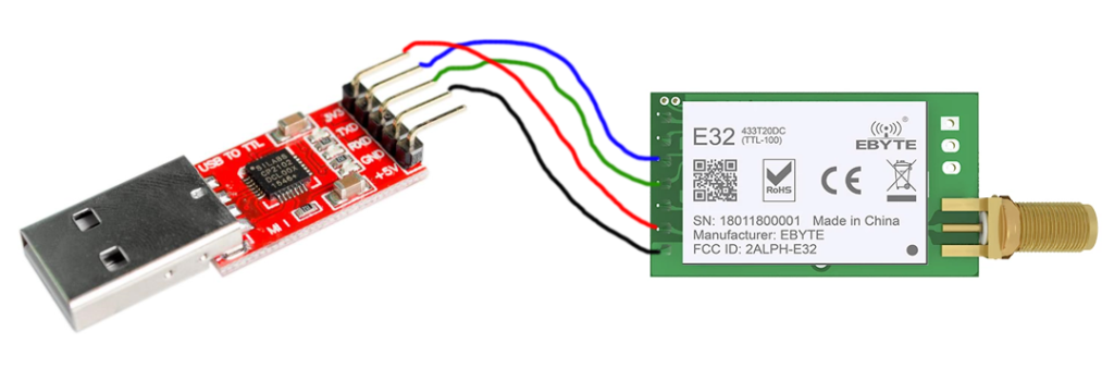
Necessary is use USB<->UART adapter, if we want use USB socket in our computer for communication with LoRa Modules.
SCHEMATIC
Below show wiring diagram. Use Wire cable to connect Power supplu VCC and GND on module with 3.3V and GND pin on adapter. For data transmission connect TX (LoRa Module board) with RX (Adapter USB-UART) and RX (LoRa Module board) with TX (Adapter USB-UART).
MODULE CONFIGURATION
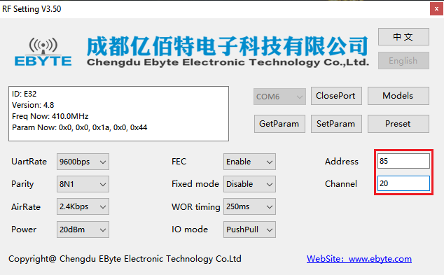
For configure the module settings we using RF Setting V3.50. This is simple app for Windows which give opportunity fast set new value for parameters like Module Address or Channel.
Connect both LoRa Modules to computer and run RF Setting application. Make sure the attached adapters have been properly detected and installed in the system. This can be checked in the Devices Manager (Windows OS). Select the first connected module from the COM list. Select OpenPort and waiting for the GetParam button will be avilable. If the communication is correct, click avilable button GetParam. The application will read the currently saved settings in the module.
Set new value of parameters for Address and Channel. For Address set value on 85. For Channel we set new value on 20. This is good place to experiment with other value for parameters. More detail about using in this project module E32-433T20DC we can find in offical datasheet.
DATA TRANSMISSION
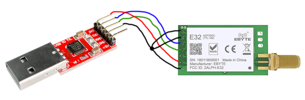
Befor connectinf with devices via UART we must hardware set the Normal Mode (mode 0) for both Modules.T o do this, connect pin number 1 (M0) and pin number 2 (M1) of the module to ground (GND). After this we can not set new value of parameters in RF Setting app. If you need change module configuration disconet M0 and M1 pin from GND.
Now we can use Serial Terminal Software e.g. RealTerm to test data transfer between radio modules. Do not forget about add Carriage Return sign for transmitted string. In RealTermi this option calle as +CR in Send card.